
Why Are CPO and NPO FAUs Important for Buyers?
Why Are CPO and NPO FAUs Important for Buyers?
As bandwidth demand rises, buyers must evaluate more than optical speed. They must also consider how fibers connect, align, and remain stable beside high-density photonic engines. A CPO/NPO FAU—the fiber array unit used with co-packaged or near-packaged optics—helps define that physical interface. Small alignment errors matter. So do connector access, assembly yield, and repair options.
Industry research provides useful context. Yole Group’s optical-transceiver market analysis tracks the growth and evolution of high-speed datacom optics. OIF’s Co-Packaging Framework Document describes the system-level challenges of bringing optical and electronic functions closer together. Neither source makes every FAU interchangeable. Buyers should compare fiber count, pitch, end-face quality, coupling loss, tolerances, and qualification data against their actual platform.
LightCounting CEO Vladimir Kozlov is a recognized analyst of optical communications markets. His public market commentary can be paraphrased as a buyer’s reminder: demand forecasts matter, but product choices still depend on deployment economics and implementation readiness. That distinction is easy to overlook. Ask suppliers for measured insertion-loss distributions, alignment tolerances, environmental test results, and a clear rework process. Request evidence from the intended package, not only a polished laboratory demonstration. A few clean samples are not production proof. And specifications alone cannot reveal how an assembly behaves during installation or service. For buyers, the CPO/NPO FAU is therefore not a minor accessory; it is a practical determinant of optical performance, manufacturability, and long-term maintainability.
What Are CPO and NPO Fiber Array Units?
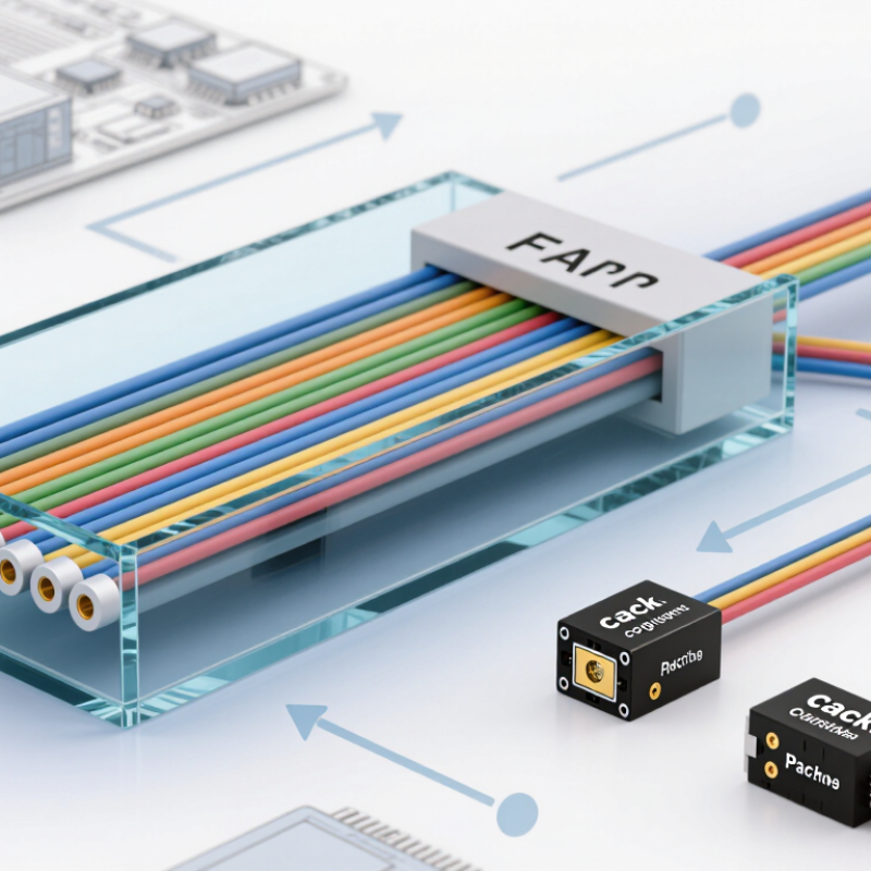
CPO and NPO fiber array units, or FAUs, are precision assemblies that position multiple optical fibers beside photonic components. Each fiber must meet a tiny optical port with controlled spacing and angle. A glass array, alignment features, and a protective housing help maintain that position. Small errors can weaken the optical signal.
In co-packaged optics (CPO), optical engines sit close to switching or computing chips within the same package. Near-packaged optics (NPO) places them nearby, but typically outside that package. In both designs, FAUs provide the physical fiber interface. They help route light between the photonic engine and external fiber connections. The exact arrangement depends on the system.
For buyers, the label alone says little about fit. Check fiber count, pitch, end-face quality, connector style, and alignment tolerances against the intended optical engine. Ask how performance is measured and whether results cover temperature changes and assembly variation. Small details matter. A drawing may look correct while the finished unit proves difficult to install. This part is easy to underestimate. It is also worth confirming handling requirements, since a clean end face and stable mounting affect repeatable coupling. Specifications can feel less tidy than expected, so request clear test conditions before comparing suppliers.
