
Why Choose Neodymium Magnets for Your Business?
A Neodymium Magnet can deliver strong holding force from a compact footprint. That matters when a motor must fit inside a tight housing, or a sensor needs a small, dependable magnetic component. For businesses, the decision is not only about strength. Operating temperature, corrosion protection, coating, shape, and supply continuity all affect performance and total cost.
The U.S. Geological Survey’s Mineral Commodity Summaries 2025 reports estimated global rare-earth mine production of 390,000 metric tons in 2024, including 270,000 metric tons in China. These figures describe rare-earth output, not magnet production, but they show why buyers should examine sourcing and supplier resilience. The U.S. Department of Energy’s 2023 Critical Materials Assessment also identifies rare earth elements used in permanent magnets as important materials for clean-energy technologies. The practical takeaway is clear: specify the grade and working conditions, not just the magnet’s advertised pull force. A magnet exposed to heat or moisture may need different properties or protective treatment. Small specification errors can become costly.
For procurement teams, compare tested performance, dimensional tolerances, coating options, and traceable documentation. Ask suppliers how they verify magnetic properties and manage batch variation. Then test samples in the actual assembly. A lab result is useful, but it cannot capture every vibration, temperature cycle, or installation constraint. Even a well-chosen magnet can disappoint when the design overlooks those details.
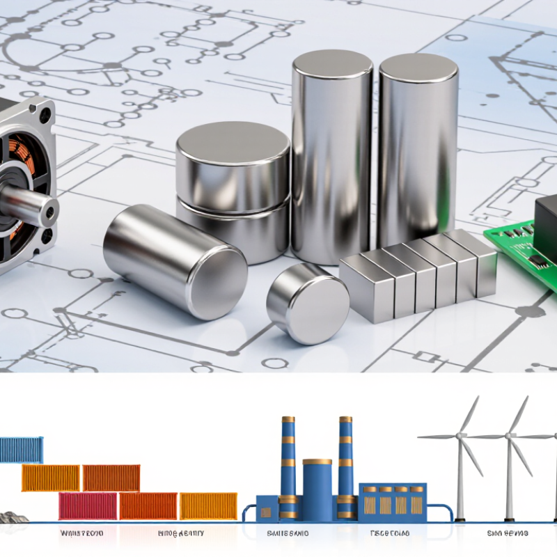
What Neodymium Magnets Are and How They Work
Neodymium magnets are permanent magnets made mainly from neodymium, iron, and boron. Their key magnetic phase, Nd₂Fe₁₄B, has a crystal structure that strongly favors magnetization in one direction. During manufacture, the material is magnetized so many tiny magnetic regions align. The result is a powerful, compact field that can hold steel parts or drive a motor. Simple, but not magic.
The USGS Mineral Commodity Summaries 2024 estimated 2023 global rare-earth mine production at 350,000 metric tons of rare-earth-oxide equivalent, including 240,000 metric tons from China. This measures mined material, not magnet output; the distinction matters when assessing supply.
For business use, check the magnet’s grade, dimensions, temperature rating, and coating. A strong magnet can lose performance when heated, and uncoated material can corrode. “Strong” alone is not a specification.
Tips: Match the magnet to the actual job. Test it near the real air gap and working temperature, not just on a clean steel bench. Keep a little margin. It is easy to overlook assembly forces, too; two magnets can snap together before a technician has time to react.
