What Is a Heatsink Thermal Pad?
A Heatsink Thermal Pad is a soft, electrically insulating interface material placed between a heatsink and a heat-producing component. It fills microscopic air gaps. Those gaps resist heat flow more than many engineers expect. The pad also accommodates uneven surfaces, mounting tolerances, and slight component movement.
Market reports show why this small layer deserves closer attention. MarketsandMarkets estimates the global thermal interface materials market could grow from approximately USD 4.1 billion in 2023 to USD 6.2 billion by 2028. Grand View Research also forecasts strong growth through 2030, although its figures differ because market definitions vary. These reports include thermal pads, pastes, films, and phase-change materials. They do not describe every Heatsink Thermal Pad application equally.
Dr. Bahgat Sammakia, a recognized thermal-management researcher, has emphasized, “Thermal management is a system-level problem, not a component-level problem.” That principle matters at the workbench. A pad with 12 W/m·K conductivity can still perform poorly if it is too thick, poorly compressed, or contaminated by dust. Conductivity numbers alone mislead. Contact resistance, pressure, surface flatness, and long-term aging also shape results.
It is not magic.
A reliable selection process examines the heat source, mounting force, gap size, operating temperature, and electrical requirements. Manufacturers should verify performance through thermal testing, not catalogue claims alone. Even careful designs can fail. Pad compression may change over time, and thermal cycling can expose weaknesses that a short laboratory test misses. A practical Heatsink Thermal Pad guide should explain these limitations clearly, helping readers choose performance over attractive specifications.
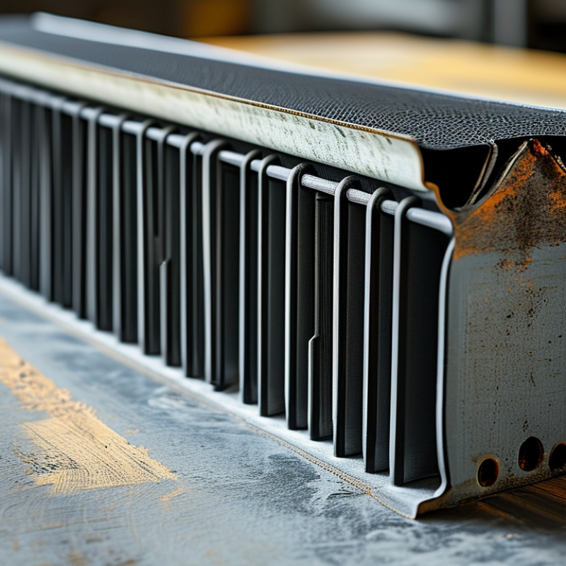
Definition and Purpose of a Heatsink Thermal Pad
What Is a Heatsink Thermal Pad?
Definition and Purpose of a Heatsink Thermal Pad
A heatsink thermal pad is a soft, thermally conductive layer placed between a heat-producing component and a heatsink. Its main purpose is to fill tiny air gaps caused by uneven metal surfaces. Air transfers heat poorly. The pad creates a more continuous path for heat to move away from the component.
Thermal pads are available in different thicknesses, hardness levels, and conductivity ratings. Some also provide electrical insulation, which helps prevent unwanted contact between conductive surfaces. In practical assembly work, thickness matters greatly. A pad that is too thin may not cover surface gaps. A pad that is too thick may increase thermal resistance or reduce mounting pressure.
Fit matters.
Technicians should check the measured gap, contact area, and expected compression before installation. The mating surfaces should be clean and free from dust, oil, and protective film. Do not stack several pads unless the design specifically allows it. Stacked layers can trap gaps and reduce performance.
A common mistake is choosing the highest conductivity rating alone. That number does not guarantee better cooling. Material softness, pressure, surface flatness, and long-term stability also influence results. Some pads may harden, shift, or lose compression after repeated heating cycles. The simple assumption is that installation is effortless, but real assemblies often need careful inspection and testing. A thermal camera or temperature sensor can reveal uneven contact that looks acceptable by eye.
How Thermal Pads Transfer Heat Between Components
What Is a Heatsink Thermal Pad?
How Thermal Pads Transfer Heat Between Components
A heatsink thermal pad is a soft, thermally conductive layer placed between a hot component and a heatsink. It fills tiny gaps caused by uneven metal surfaces. Without it, trapped air can block heat more effectively than many people expect. Air is a poor heat conductor.
The pad transfers heat through direct contact. Heat moves from the component into the pad, then into the heatsink. Compression matters because it improves surface contact and removes small air pockets. In practical assembly, I check the pad thickness carefully. A pad that is too thin may not fill the gap. One that is too thick can reduce contact pressure and increase thermal resistance.
Small details matter. The mounting surface should be clean and free from dust, oil, and protective film. The pad should cover the heat source without folding over its edges. I have occasionally seen a pad installed with uneven pressure, leaving a warmer corner near the component. That result is easy to overlook. A simple temperature check can reveal it.
Thermal pads do not remove heat by themselves. They only provide a better path toward the heatsink. Their performance depends on conductivity, thickness, compression, and surface contact. Laboratory ratings can help, but real assemblies may perform differently. That is why measured temperatures remain important during testing.
Types and Materials Used in Thermal Pads
What Is a Heatsink Thermal Pad?
Types and Materials Used in Thermal Pads
A heatsink thermal pad fills microscopic gaps between a hot component and its heatsink. It improves contact without liquid mess or complicated application. Most pads are supplied as soft sheets with controlled thicknesses, often from 0.5 to 3 millimeters. Compression matters. A rigid pad can leave air pockets, while an overly soft pad may squeeze out during assembly.
Silicone-based pads remain widely used because they combine flexibility, electrical insulation, and stable performance. Typical thermal conductivity ranges from 1 to 12 W/m·K. Non-silicone pads can reduce contamination concerns in optical or sensitive electronics. Phase-change pads soften when heated, improving surface contact after installation. Graphite pads provide excellent in-plane heat spreading, but they may conduct electricity. That detail can damage exposed circuits.
The choice should match pressure, surface roughness, temperature, and voltage isolation requirements. ASTM D5470 testing is commonly used to measure thermal resistance, although laboratory results may not match a finished device. MarketsandMarkets’ 2024 thermal interface materials report identifies electronics cooling and high-power computing as major growth areas. Grand View Research also reports strong market expansion through 2030, driven by denser electronics. Numbers vary between reports. That is worth questioning.
In practical assembly, a 6 W/m·K pad may outperform a 12 W/m·K pad if it compresses poorly. Measure the gap first. Then verify pressure and aging behavior. Surface oils, uneven screws, and repeated thermal cycling can quietly reduce performance.
What Is a Heatsink Thermal Pad?
A heatsink thermal pad is a compliant thermal interface material that fills microscopic air gaps between a heat-generating component and a heatsink. The chart compares representative thermal conductivity values for common thermal pad material types.
Higher thermal conductivity generally improves heat transfer, but real-world performance also depends on pad thickness, compression, surface flatness, electrical insulation, and contact pressure. Values shown are representative midpoints of commonly published material ranges and may vary by formulation.
How to Choose the Right Thermal Pad
What Is a Heatsink Thermal Pad?
A heatsink thermal pad fills microscopic gaps between a chip and its heatsink. Unlike paste, it offers controlled thickness and cleaner installation. Choosing the right pad matters because cooling efficiency depends on more than thermal conductivity. ASTM D5470 testing evaluates thermal resistance under defined pressure and temperature conditions. Therefore, compare test conditions, not only the printed W/mK value.
How to Choose the Right Thermal Pad
Start with the measured gap. A 1 mm pad forced into a 2 mm space may lose contact. Excess compression can also stress fragile components. For example, a 1 mm pad rated at 6 W/mK across 1 cm² has an ideal resistance near 1.67 K/W. Real assemblies perform worse because surfaces are uneven and pressure varies. The U.S. Department of Energy reports that cooling can represent about 40% of data-center electricity use. Small interface improvements can therefore matter at scale. Still, a higher conductivity rating is not automatically better. Softness, compression recovery, electrical insulation, and long-term pump-out resistance deserve equal attention.
Tips: Check the actual gap with a thickness gauge or compressed modeling clay. Confirm the pad’s compression range and dielectric strength. Review ASTM D5470 results at comparable pressure. I have seen installation errors outweigh impressive material specifications. Clean both surfaces, avoid stretching the pad, and inspect contact marks after assembly. A thicker pad may fit better, but it can also increase thermal resistance.
What Is a Heatsink Thermal Pad? - How to Choose the Right Thermal Pad
A heatsink thermal pad is a compliant thermal interface material used to fill microscopic air gaps between a heat-producing component and a heatsink. The comparison below summarizes common pad types and key selection criteria.
Thermal Pad Types and Selection Guide | Pad Type | Typical Thermal Conductivity | Typical Thickness | Approx. Thermal Resistance at 1 mm | Electrical Property | Compressibility and Conformability | Best Applications | Main Considerations |
| Standard Silicone Gap Pad | 1–3 W/m·K | 0.5–5 mm | 約 3.3–10 K·cm²/W | Usually electrically insulating | Soft to medium; accommodates uneven surfaces and small gaps | General electronics, power supplies, LED modules, and control boards | Economical and easy to install, but not ideal for very high heat loads |
| High-Conductivity Silicone Pad | 3–12 W/m·K | 0.5–3 mm | 約 0.8–3.3 K·cm²/W | Usually electrically insulating | Medium to highly conformable; requires controlled compression | Processors, power semiconductors, motor controllers, and battery systems | Higher conductivity can increase cost and reduce softness |
| Phase-Change Thermal Pad | 3–8 W/m·K | 0.1–0.5 mm | 約 1.3–3.3 K·cm²/W | Often electrically insulating; verify the specification | Softens when heated and fills fine surface irregularities | Flat, well-mated surfaces with repeatable assembly pressure | Needs suitable activation temperature and adequate clamping force |
| Graphite Thermal Sheet | In-plane: 200–1,500 W/m·K
Through-plane: commonly much lower | 0.025–0.2 mm | Direction-dependent; do not estimate from in-plane value | Electrically conductive | Thin and flexible, but generally poor at filling large gaps | Heat spreading across flat surfaces and compact electronic assemblies | Requires electrical isolation and careful orientation due to anisotropic conductivity |
| Electrically Conductive Silicone Pad | 2–6 W/m·K | 0.5–3 mm | 約 1.7–5 K·cm²/W | Electrically conductive or partially conductive | Medium; can conform to moderate surface gaps | Applications where thermal transfer and electrical grounding are both required | Must be kept away from exposed conductors unless grounding is intentional |
Key Factors for Choosing a Thermal Pad
| Selection Factor | What to Check | Practical Guidance |
| Gap Thickness | The measured distance between the component and heatsink | Select a pad that matches the actual gap without excessive compression or bending |
| Thermal Conductivity | Through-plane conductivity in W/m·K | Use a higher value when heat flux is high, but remember that thickness and contact resistance also affect performance |
| Electrical Isolation | Dielectric strength and volume or surface resistivity | Choose an electrically insulating pad for exposed power pins, contacts, or conductive heatsinks |
| Compression | Recommended compression range and compressive stress | Confirm that the enclosure, clips, or screws can provide uniform pressure without damaging the component |
| Temperature Range | Continuous and peak operating temperatures | Check the complete assembly temperature range, including storage, cycling, and any phase-change activation temperature |
| Surface Flatness | Flatness, roughness, contamination, and surface oxidation | Clean both surfaces and avoid unnecessary pad thickness, which increases thermal resistance |
Note: Thermal resistance values are approximate examples calculated for a 1 mm pad using thickness divided by thermal conductivity. Actual performance also depends on contact resistance, compression, surface flatness, pressure, and assembly quality.
Installation, Maintenance, and Common Limitations
A heatsink thermal pad fills microscopic gaps between a chip and its heatsink. Its value depends on installation quality, not conductivity alone. Clean both surfaces with high-purity isopropyl alcohol, then let them dry completely. Measure the original gap before choosing pad thickness. A pad that is too thin leaves air pockets. One that is too thick can tilt the heatsink.
Pressure matters. Apply even mounting pressure and follow the assembly torque specified by the equipment maker. Do not stretch, fold, or reuse a compressed pad.
In practical maintenance, inspect pads after thermal cycling, fan failure, or heatsink removal. Look for hardening, oil separation, tearing, or uneven contact marks. Replace damaged material, even when the system still operates. Small defects grow quietly.
Thermal pads also have clear limits. Their conductivity is usually lower than a well-applied liquid interface material, and poor compression raises thermal resistance. The U.S. Department of Energy reports that cooling can consume up to 40% of data-center electricity, showing why small thermal losses deserve attention. However, pad replacement alone cannot correct blocked airflow or an undersized heatsink. The 2024 Uptime Institute Global Data Center Survey reported an average PUE of 1.56, although PUE does not isolate pad performance. JEDEC JESD51-14 also emphasizes standardized thermal testing, not assumptions from a product label. I sometimes trust conductivity numbers too quickly. Contact pressure and gap control often matter more.