
What Is a Rotary Actuator Symbol?
A Rotary Actuator Symbol is more than a small mark on an engineering drawing. It represents a device that converts fluid, pneumatic, or electrical energy into controlled rotary motion. In a schematic, that compact graphic may identify turning direction, shaft movement, operating medium, and control conditions. A clear symbol helps engineers read the system before touching the equipment.
This matters in modern automation. The International Federation of Robotics reported 541,302 industrial robots installed worldwide in 2023 in its World Robotics 2024 report. Many robotic cells depend on rotary actuators for gripping, indexing, positioning, and valve control. Their drawings must communicate quickly across design, manufacturing, maintenance, and procurement teams. ISO 1219-1 and ISO 1219-2 provide established graphical rules for fluid-power systems. IEC 60617 also supports consistent electrotechnical symbols and database-based documentation.
However, a Rotary Actuator Symbol is not always universal. Its meaning depends on the drawing standard, actuator technology, and additional control symbols nearby. A vane actuator may appear differently from a rack-and-pinion actuator. Electrical rotary actuators may require motor, feedback, and limit-switch indicators. Small details matter. A missing arrow can obscure rotation direction. An unclear port label can delay commissioning.
This guide explains how to identify the symbol, interpret its functional elements, and compare common schematic conventions. It also considers practical documentation problems. Even experienced engineers can misread simplified graphics. That is worth remembering. Reliable interpretation requires checking the legend, applicable standard, datasheet, and actual actuator configuration before making technical decisions.
Definition and Purpose of a Rotary Actuator Symbol
What Is a Rotary Actuator Symbol?
Definition and Purpose of a Rotary Actuator Symbol
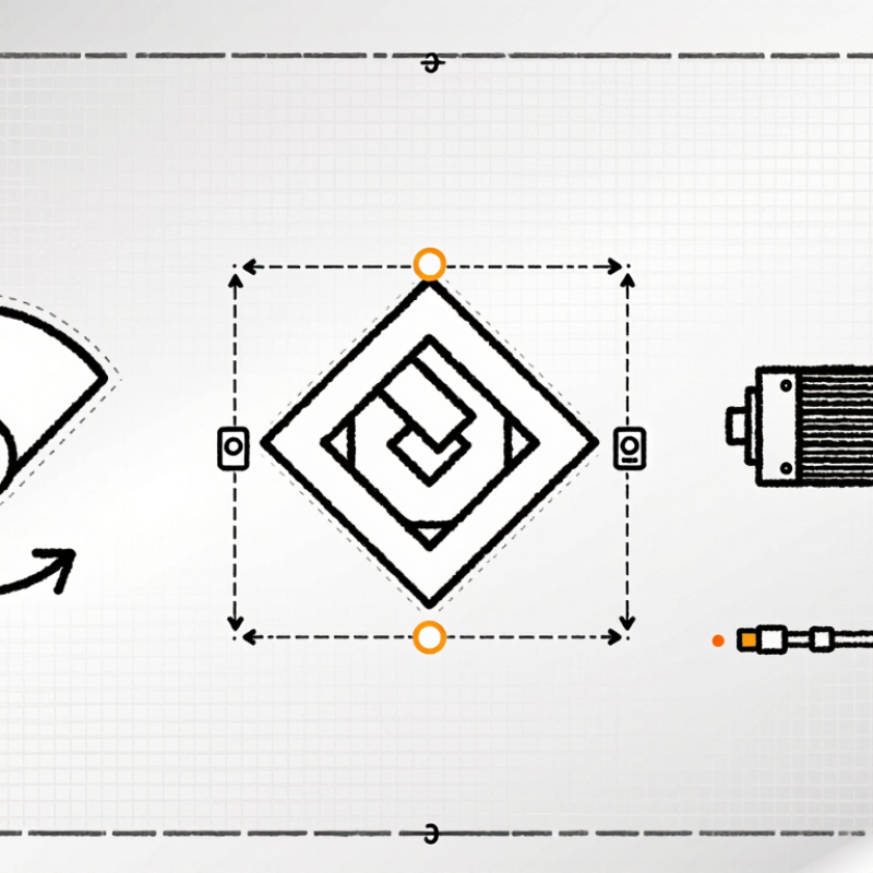
A rotary actuator symbol is a simplified graphic used in pneumatic, hydraulic, or electrical schematics. It represents a device that converts fluid pressure or electrical energy into rotary motion. The symbol helps engineers identify movement without drawing the actuator’s physical housing, shaft, or internal parts.
In a pneumatic diagram, the symbol often shows a circular body with an arrow, shaft, or curved motion mark. These details indicate rotation, direction, or adjustable travel. A double-headed arrow may suggest reversible movement. A single arrow can indicate one-way rotation, although conventions differ between standards. The drawing alone is not enough. Always check the diagram legend.
The purpose is practical. Technicians can trace motion from a valve to an actuator and then to a machine component. This makes troubleshooting faster during commissioning or maintenance. For example, a curved arrow beside a shaft may show that a gripper turns 90 degrees. A small spring mark may indicate a return mechanism. Symbols also reduce clutter on complex equipment drawings.
In real schematic reviews, unclear symbols can cause costly assumptions. I have found that even experienced readers may interpret a rotation arrow differently. That is worth questioning. Engineers should confirm the applicable drafting standard, actuator type, rotation angle, and control method before installation. A correct symbol supports reliable communication, but it cannot replace detailed specifications.
