
What Are Granite Support Blocks Used For?
granite support blocks are compact, load-bearing pieces used to stabilize and elevate heavy structures. They commonly support countertops, masonry walls, outdoor kitchens, steps, monuments, and landscape features. Their dense stone composition handles substantial weight while resisting moisture, abrasion, and temperature changes. In practical installations, these blocks can distribute pressure across a broader surface. They may also reduce direct contact between a structure and wet soil or concrete.
A well-made block should have consistent dimensions, sound edges, and no deep cracks. Small defects can become serious under concentrated loads. Installers often place granite support blocks beneath posts, slabs, or precast components, then check alignment with a level. Thin shims may correct minor differences, but they should not replace proper sizing or stable foundations. Drainage matters too. Standing water can affect surrounding materials, even when granite itself remains durable.
Granite support blocks are not a universal solution. Their weight makes handling difficult, and rough surfaces may damage softer materials. I have seen projects focus on appearance while overlooking load paths and access for future repairs. That mistake is easy to make. A qualified contractor or structural professional should review unusual loads, elevated structures, and local building requirements. The correct block depends on weight, dimensions, soil conditions, exposure, and the supported material. Used thoughtfully, granite support blocks provide a durable, clean-looking foundation. Their performance still depends on careful design and installation.
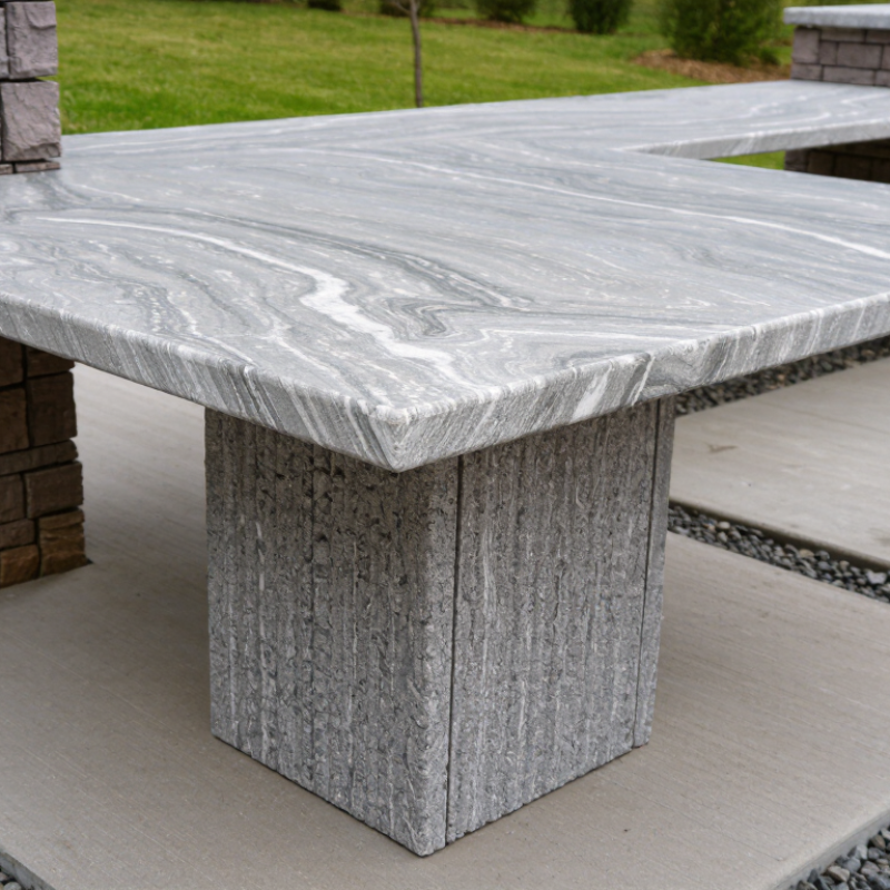
Definition and Basic Function of Granite Support Blocks
Granite support blocks are compact load-bearing pieces placed beneath granite slabs, edges, seams, and overhangs.
Their basic function is to transfer weight into the cabinet, wall, or structural frame. They also limit bending, vibration, and stress around vulnerable areas such as sink cutouts.
A 2.4-meter by 0.6-meter granite slab, 30 millimeters thick, can weigh about 115 kilograms. The exact weight changes with density and moisture.
Placement matters. Blocks should provide continuous, stable contact rather than touch the stone at one small point.
The Natural Stone Institute’s Dimension Stone Design Manual advises evaluating span, overhang, slab thickness, substrate, and joint location before selecting support.
A simple rule can mislead. A thick block may still fail when the cabinet is uneven or the adhesive bond is weak.
The 2024 U.S. Geological Survey Mineral Commodity Summaries placed U.S. dimension-stone production in the million-ton range for 2023, showing the scale of material used in construction.
That volume does not remove the need for site-specific checks.
Granite support blocks help prevent cracking, but they cannot correct poor installation.
On site, the weak point is often the contact surface, not the granite itself. Clean alignment, firm bearing, and measured overhangs remain essential. Small errors matter.
