
What Are the Top Aluminum Extrusion Die Types in 2026?
In 2026, choosing an Aluminum Extrusion Die means balancing profile design, alloy, production volume, and finishing requirements. The right die helps shape heated aluminum into consistent profiles, from simple flat bars to hollow window frames. Yet no single design suits every job. The cross-section often determines the die type, while press capacity and operating conditions influence how well it performs.
This guide introduces the main options: solid dies for non-hollow shapes, hollow dies for enclosed sections, and semi-hollow dies for profiles with narrow openings. It also covers bridge and porthole designs, which form hollow shapes by splitting and rejoining the aluminum inside the die. Each approach has practical trade-offs in tooling complexity, metal flow, surface quality, and maintenance. Small details matter.
A drawing alone cannot reveal every production challenge. Wall thickness, sharp corners, and uneven metal flow may affect both feasibility and consistency. Even experienced teams sometimes revise a profile after trial runs. That is worth remembering. For reliable comparisons, consider manufacturer guidance and actual press conditions, not just a die’s label or initial price. The sections ahead explain how these die types work, where they are commonly used, and what to check before specifying one.
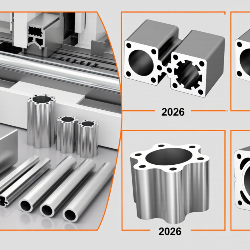
How Die Geometry Governs Aluminum Extrusion at Ratios of 10:1–100:1
What Are the Top Aluminum Extrusion Die Types in 2026?
In 2026, aluminum extrusion die selection depends heavily on profile geometry and extrusion ratio. Die geometry matters more than a catalog label. At ratios from 10:1 to 100:1, small design choices can change pressure, temperature, and surface quality. Solid dies work well for uncomplicated bars and channels. Hollow profiles usually require porthole or bridge dies, especially when internal walls must remain stable.
A porthole die divides billet flow through several ports before welding it inside the chamber. Bridge dies support delicate cores, but their webs can create visible weld lines. For complex profiles, multi-cavity dies may improve output, yet they demand balanced metal flow. Bearing length is critical. A long bearing can control dimensions, but it also increases friction and die load. Unequal wall thickness makes this harder. Thin sections may cool quickly, while heavy corners stay hot. I have seen a mathematically balanced design fail during production because the bearing adjustments were too conservative.
Tips: Start with the real profile ratio, not an estimate. Check the thinnest wall, hollow area, corner radius, and expected billet temperature. Use simulation when the ratio approaches 50:1 or higher. Then confirm the result with a short trial extrusion. A perfect model is still only a model. Inspect weld seams, exit speed, and die wear after production. Small corrections often outperform a complete redesign.
| Die type | Typical section geometry | How the die geometry controls flow | Indicative extrusion-ratio band | Common design considerations |
|---|---|---|---|---|
| Solid (flat) die | Profiles without enclosed internal cavities, such as bars, angles, channels, and simple shapes. | Bearing lengths balance metal flow across the profile. Longer bearings generally add flow resistance; local bearing adjustments can help compensate for uneven flow. | 10:1–60:1 | Useful for a broad range of sections. Thin walls, sharp corners, and large differences in local section thickness can make flow balancing more demanding. |
| Hollow porthole (bridge) die | Hollow profiles with one or more enclosed voids, such as tubes and multi-cell sections. | Ports divide the incoming metal into streams. The streams pass around bridges and recombine in a welding chamber before exiting through the die orifice. | 10:1–40:1 | Bridge strength, port area, chamber design, and billet conditions affect pressure and weld quality. Applications requiring pressure-tight performance need suitable process qualification and testing. |
| Mandrel hollow die | Hollow sections formed around a mandrel, commonly for tube-like products. | The mandrel creates the internal shape while the surrounding die opening defines the outside dimensions. Alignment and concentric flow are central to wall-thickness control. | 10:1–35:1 | Mandrel support, stiffness, alignment, and material flow around the mandrel influence dimensional consistency. The practical design depends on section size and press setup. |
| Semi-hollow die | Sections with a partially enclosed cavity and a relatively narrow opening. | The narrow opening increases resistance and can create an asymmetric flow path. Bearing and cavity geometry are used to balance flow while maintaining die strength. | 10:1–30:1 | As the opening narrows or the cavity becomes deeper, die deflection and local flow variation become more important design checks. |
| Tongue die | Open or partly enclosed profiles with a slender tongue or projecting die feature. | A thin tongue forms a narrow slot or cavity but is exposed to high pressure and bending loads. Its thickness, unsupported length, and surrounding metal flow limit practical geometry. | 10:1–25:1 | Often selected when the profile shape cannot be made with a simple flat die. Tongue strength and deflection require careful evaluation; the ratio band is especially geometry-dependent. |
| Multi-hole die | Several small, usually similar, profiles extruded in one billet stroke. | Multiple openings divide the total flow among profile strands. Hole layout, spacing, and bearing balance help keep strand speeds and temperatures reasonably uniform. | 20:1–100:1 | High overall ratios are possible with small sections, but depend on alloy, press capacity, billet conditions, and total exit area. Ratio should be calculated using the combined area of all openings. |
Reading the ratio bands: Extrusion ratio is the billet-container cross-sectional area divided by the total extrudate cross-sectional area. The ranges shown are indicative planning bands, not fixed limits or standards; achievable ratios depend on alloy, billet temperature, press capability, profile complexity, and die design.
