
7 Tips for Choosing the Right Oilfield Mud Pump?
Choosing the right Oilfield Mud Pump affects drilling continuity, crew safety, fluid control, and long-term operating costs. A pump may look suitable on paper, yet struggle when abrasive solids, high mud weight, or unstable formations enter the system. The decision requires more than comparing horsepower and purchase prices. It demands careful attention to flow rate, discharge pressure, liner size, stroke length, and expected duty cycles.
Small details matter. A pump running near its pressure limit may create excessive vibration, heat, and premature wear. An undersized pulsation dampener can make pressure fluctuations worse. Field teams should also examine maintenance access, spare-parts availability, seal performance, and the supplier’s technical response time. These factors often determine whether a pump remains productive during a demanding drilling phase. Do not ignore the mud system.
This guide presents seven practical tips for evaluating pump options. It considers operating conditions, fluid characteristics, reliability, energy use, and total ownership cost. Manufacturer data should be checked against site measurements and verified by qualified drilling or mechanical professionals. A neat specification sheet can still mislead. Real performance depends on installation quality, operator habits, mud treatment, and maintenance discipline. Some recommendations may also require adjustment because every well has different pressure demands and environmental conditions. The strongest choice is not always the largest pump. It is the pump that delivers stable performance, manageable maintenance, and dependable support throughout the project.
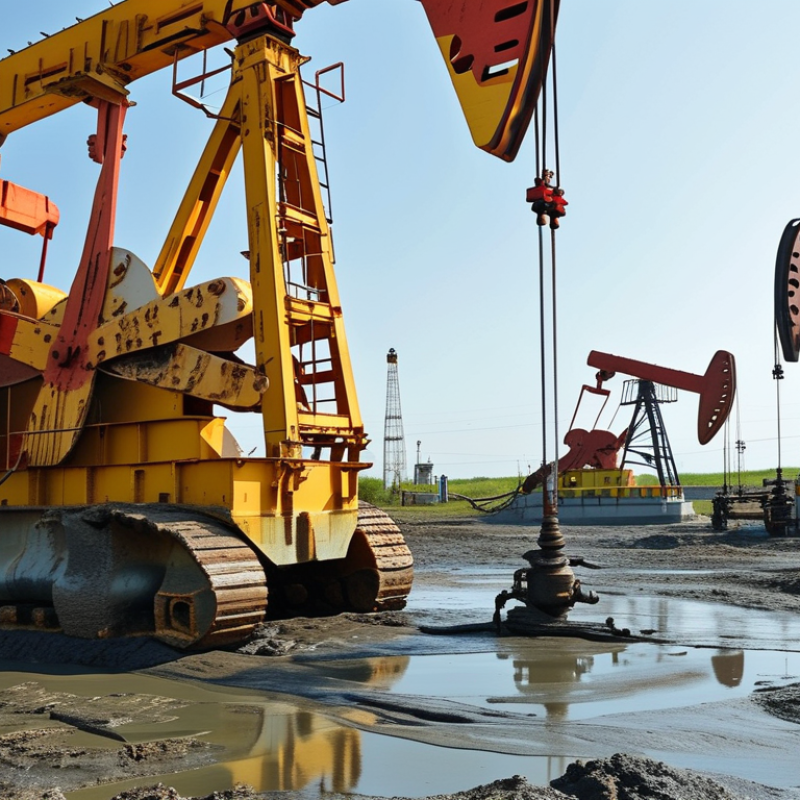
Oilfield Mud Pumps: Types, Functions, and Key Operating Principles
Selecting the right oilfield mud pump starts with understanding its job. The pump moves drilling fluid through surface lines, the drill string, and the bit. That flow carries cuttings upward and cools the drilling tools.
Triplex plunger pumps are common because they provide high pressure with relatively steady discharge. Duplex pumps can offer strong suction performance and simpler maintenance, but their flow pulsation may require extra control. Centrifugal pumps usually support low-pressure transfer duties, such as mixing or feeding, rather than deep well circulation. The choice depends on required flow rate, working pressure, fluid density, and expected operating hours.
The operating principle is straightforward. A crankshaft converts rotary motion into reciprocating plunger movement. During the suction stroke, the inlet valve opens and the fluid chamber fills. During the discharge stroke, the outlet valve opens under pressure. Liners, pistons, valves, and seals control efficiency. Small wear can cause pressure loss, heat, and unstable flow.
Watch the gauge.
Field checks should include suction stability, vibration, liner condition, and pulsation dampener pressure. A pump rated for extreme pressure is not automatically the best choice. Oversizing may increase fuel use and maintenance costs. Undersizing can create dangerous pressure spikes and poor hole cleaning. In practice, fluid abrasiveness often changes the calculation. I have seen apparently suitable pumps struggle when solids content was underestimated. That mistake deserves more attention. Temperature, spare-part access, and crew skill also influence reliability. Performance data should be verified under realistic mud conditions, not only laboratory water tests.
