
10 Tips for Buying a P10 LED Panel
A P10 Led Panel has a pixel pitch of 10 millimeters, making it a practical option for large-format signs viewed from a distance. From across a parking lot, the image may look crisp; from a few steps away, individual pixels become easier to notice. Viewing distance matters.
The wider LED market is growing. Grand View Research estimated the global LED display market at USD 7.5 billion in 2023 and projected an 8.6% compound annual growth rate from 2024 to 2030. That estimate covers many display types, not P10 products alone. Still, it shows why buyers face more choices—and more specifications to compare. A market forecast cannot tell you whether one panel suits your site.
This guide presents ten practical checks before purchase. It covers brightness, weather protection, refresh rate, cabinet construction, power use, control systems, maintenance access, and warranty terms. Ask for real operating details, not just a bright showroom demonstration. Check the screen under the lighting and viewing conditions it will actually face. Request a sample or recent installation references when possible. A low price can look persuasive. It may also conceal compromises in serviceability or component quality. One point is easy to miss: the best specification sheet does not guarantee the best fit. Your site, content, installation plan, and support needs should shape the decision.
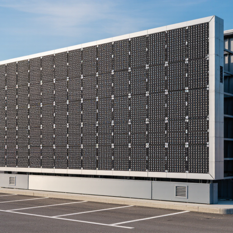
Define the Display’s Purpose, Viewing Distance, and Installation Site
A P10 panel has 10-millimetre pixel spacing, or about 100 pixels per metre. That resolution can work well for bold graphics and large text viewed from a distance. Purpose changes everything. For roadside messaging, prioritize quick readability; for a courtyard screen, consider longer viewing and mixed content. The Outdoor Advertising Association of America reported $9.1 billion in U.S. out-of-home advertising revenue for 2023. That figure signals a large market, not a guarantee that a particular screen will reach its audience.
Use 10 metres as a rough starting point for viewing distance, not a fixed rule. At that range, P10 pixels appear less distinct; closer viewers may notice them, especially in small text or detailed images. Walk the actual audience route and check sightlines from seated and standing positions. Measure it twice. I would not trust a rule of thumb alone: eyesight, content, and ambient light all change what looks clear.
The installation site sets practical limits. Note direct sun, shade, wind exposure, nearby walls, and access for maintenance. A bright outdoor location may need a higher-brightness panel, while a shaded indoor space may not. Record the mounting height and available power before comparing quotes. Small oversight: a screen can fit the wall yet remain hard to see behind a tree, sign, or passing vehicle. Recheck the view at the hours people will actually use the space.
