
What Is an SMT Reflow Oven and How Does It Work?
A Smt Reflow Oven is the controlled heating system behind most modern surface-mount assembly lines. It bonds electronic components to printed circuit boards through carefully managed solder paste. The process looks simple from outside. A board enters on a conveyor, passes through heated zones, and exits with soldered components. Inside, the temperature changes gradually and deliberately.
The oven normally includes preheating, soaking, reflow, and cooling zones. During preheating, moisture and thermal stress are reduced. The soak zone activates the flux and balances temperature across the board. In the reflow zone, solder particles melt briefly, often near the paste manufacturer’s recommended peak temperature. Cooling then solidifies the joints. Small thermocouples attached to test boards help engineers measure the real thermal profile. Not just the display temperature.
Practical experience shows that a successful profile depends on more than oven settings. Board thickness, copper distribution, component size, solder paste, and conveyor speed all influence the result. A large ground plane may absorb heat slowly, while a small component can overheat quickly. Operators often inspect solder joints under magnification and compare results with IPC-based quality guidance. Still, the process is not perfectly predictable. A profile that works well today may need adjustment after a component change or seasonal temperature shift. That limitation matters. Understanding how an Smt Reflow Oven transfers heat helps engineers make safer adjustments, reduce defects, and build more reliable assemblies.
What Is an SMT Reflow Oven?
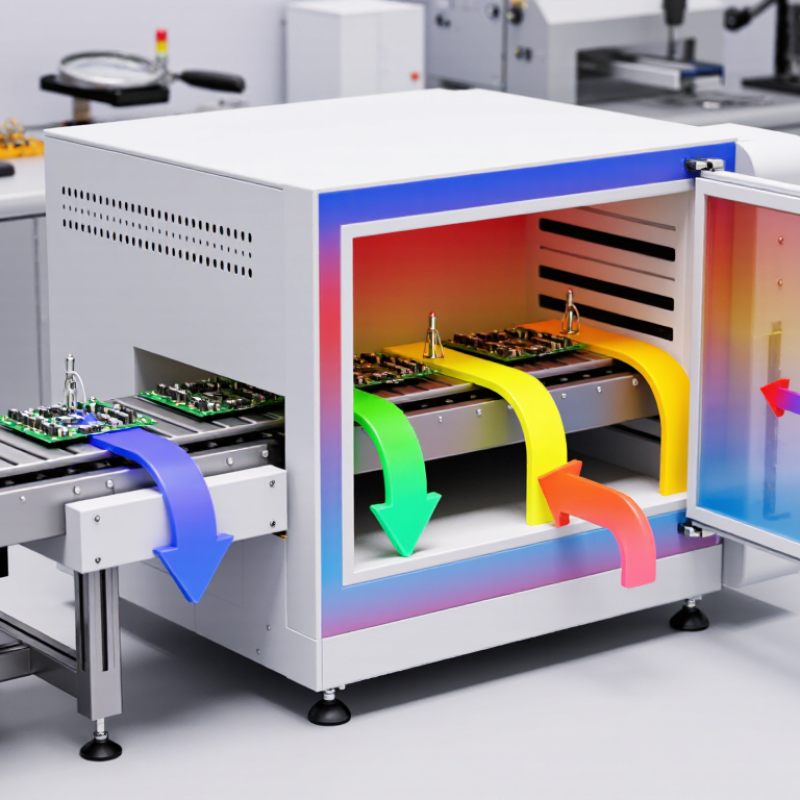
An SMT reflow oven is a controlled heating system used to solder surface-mount components onto printed circuit boards. It does not simply “bake” a board. Instead, it moves the assembly through carefully managed temperature zones. Solder paste first softens, then melts, and finally cools into solid joints. This process connects tiny component terminals with copper pads on the circuit board.
A typical oven includes preheating, soaking, reflow, and cooling zones. In the preheat area, the board temperature rises gradually, reducing thermal shock. The soaking zone helps spread heat through different materials and activates the paste chemistry. During reflow, the solder passes its melting point for a controlled period. Cooling then forms the final joint. Conveyor speed, airflow, zone temperatures, and board loading all affect the result.
Small details matter. A thermocouple attached near a large connector can reveal uneven heating that the oven display misses. Too much heat may damage components or warp the board. Too little heat can create weak, dull, or incomplete joints. A profile that works for one board may fail on another. That is why technicians compare measured profiles with solder paste data and component limits. The process is reliable, but not automatic. Even a well-maintained oven needs regular inspection, calibration, and human judgment. Some production teams rely too heavily on preset recipes, which is convenient but worth questioning.
