Top 10 Diaphragm Wall Equipment Manufacturers Worldwide
Diaphragm Wall Equipment helps contractors build deep, reinforced concrete barriers in crowded urban sites, transport corridors, and below-ground structures. The work is demanding. A stable trench, reliable slurry circulation, and accurate panel alignment all matter. Small equipment choices can affect the entire sequence.
Geotechnical engineer Ralph B. Peck is often credited with the observation, “The most important single factor in the design of a structure is the nature of the ground on which it is to be built.” That principle applies to equipment selection, too. Ground conditions, required wall depth, panel dimensions, and site access shape the choice between grab systems and hydromills. Buyers also need to examine cutter control, slurry plants, lifting capacity, spare-part access, and local service support. Specifications on paper are useful, but field support can be decisive.
This guide introduces ten manufacturers active in the worldwide market. It compares their equipment ranges and practical considerations, rather than treating any ranking as universal. Product availability and service coverage can change by region. A machine that suits one project may be poorly matched to another. That is worth remembering. The strongest choice is usually the one that fits the ground, project method, and contractor’s operating experience—not simply the most powerful model.
Diaphragm Wall Equipment: Main Types and Applications
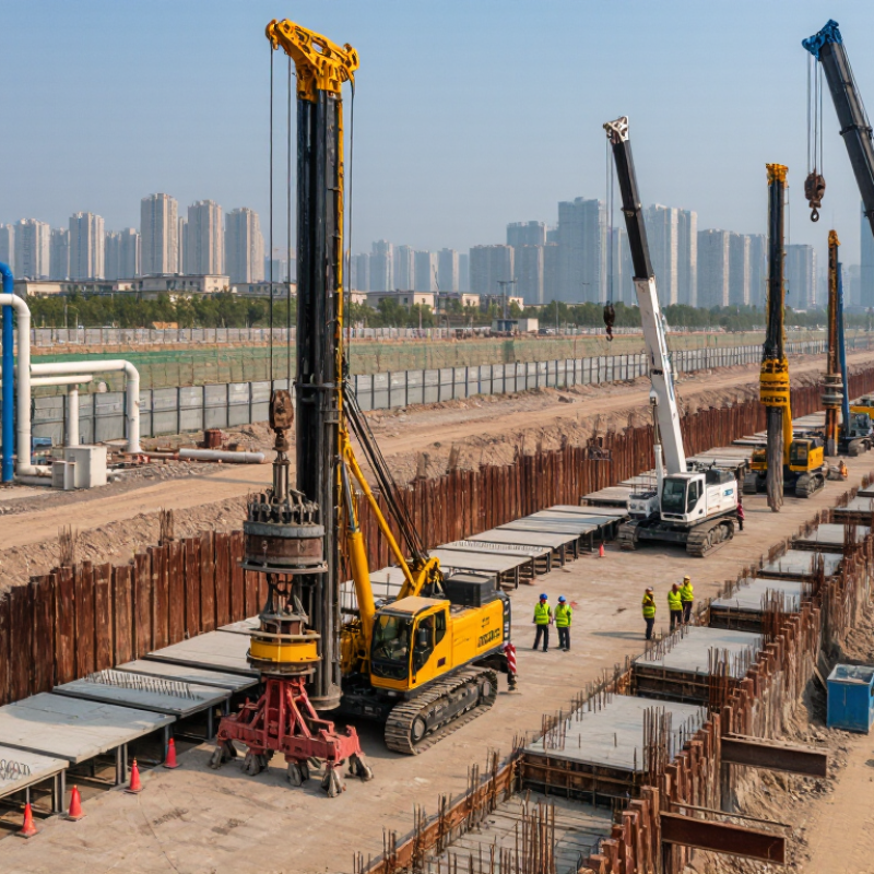
Diaphragm wall equipment creates deep, continuous support walls where space is tight and excavation loads are high. A hydraulic grab removes soil in rectangular panels, often in layered ground. A cutter, sometimes called a hydromill, handles deeper or harder formations and can deliver more consistent panel alignment. Ground conditions decide. Neither method suits every site.
Support equipment matters just as much. Slurry mixing and recycling plants keep bentonite or polymer fluid within workable limits, while desanders remove soil particles before reuse. Crawler cranes lower grabs, cutters, and reinforcement cages. Tremie pipes place concrete from the panel base upward, displacing the slurry. Watch the slurry carefully. Poor control can affect wall cleanliness and concrete quality.
These systems serve underground parking structures, metro stations, utility shafts, ports, and flood-protection works. In dense city sites, panels may sit close to existing foundations, so positioning accuracy and vibration control are practical concerns. Equipment selection depends on wall depth, soil profile, groundwater, access, and required tolerances. A tidy specification can still mislead; actual ground often changes during excavation. Allowing room for maintenance and spoil handling can prevent avoidable delays.
