
2026 How to Choose the Right Mechanical Shaft Seal?
Choosing the right Mechanical Shaft Seal in 2026 starts with the operating conditions, not a catalog photo. A seal that performs well on clean water may fail quickly with abrasive slurry, hot oil, or frequent starts. Small details matter. Even a slight change in temperature or shaft movement can affect leakage and service life.
Before comparing designs, record the fluid, pressure, temperature, shaft speed, and expected operating cycles. Check the pump or mixer manual for shaft dimensions, allowable runout, and seal-chamber limits. These details help narrow choices such as single or dual seals, balanced designs, and suitable face materials. Silicon carbide, carbon, and ceramic each behave differently; compatibility depends on the fluid and operating conditions. Ask the supplier for documented material compatibility and performance limits, rather than relying on a broad product description.
Installation matters, too. Poor alignment, contaminated faces, or dry running during startup can damage even a correctly specified seal. There is no perfect choice from a catalog alone. In practice, an initial specification may need revision when field measurements reveal conditions that were missed. Compare the proposed seal with the equipment manufacturer’s requirements, and confirm any assumptions with a qualified seal specialist. This guide explains how to weigh reliability, maintenance needs, and total operating cost, so your selection fits the equipment—not just the purchase price.
Assess the Equipment, Fluid, and Operating Conditions
2026 How to Choose the Right Mechanical Shaft Seal?
Assess the Equipment, Fluid, and Operating Conditions
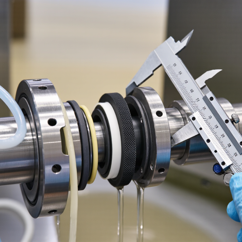
Choosing a mechanical shaft seal starts with the machine, not the catalog. Record the shaft diameter, speed, alignment, and space available around the seal chamber. Check whether the pump runs continuously, starts often, or sits idle between batches. Small details matter. Vibration, bearing wear, or a worn sleeve can shorten seal life even when the seal type seems suitable.
Next, identify the fluid as it actually reaches the seal. Note its temperature, pressure, viscosity, solids, and tendency to crystallize or change when exposed to air. Water with fine abrasive grit behaves differently from clean water; a sticky process fluid may leave deposits on seal faces. Ask operators about flush plans, cleaning cycles, and brief dry-running events. Those observations help. Fluid names alone can mislead.
Operating conditions complete the picture. Compare normal values with startup peaks and upset conditions, including pressure reversals and temperature swings. Confirm that the seal materials tolerate the fluid and heat, and that face loading suits the pressure and speed. Use equipment drawings and measured data where possible, but question old records; the process may have changed. Measurements are not always tidy. Document assumptions, then review them with maintenance and process staff before specifying a seal.
