
What Are Electrical Diagnostic Tools Used For?
Electrical Diagnostic Tools help technicians find faults that are difficult to see directly. A digital multimeter can measure voltage, resistance, and continuity. A clamp meter checks current without disconnecting a conductor. Insulation testers assess whether insulation is leaking current, while thermal cameras reveal unusual heat around terminals, motors, and circuit breakers. Each tool answers a different question. None gives a complete diagnosis by itself.
In practice, these tools support troubleshooting in homes, workshops, vehicles, and industrial systems. A technician might compare readings across a circuit, inspect a warm connection, then consult the equipment’s wiring diagram. That evidence can distinguish a loose terminal from a failed component or an overloaded circuit. The details matter. A reading taken at the wrong point, with the wrong range, or using an unsuitable instrument can mislead. Even a clear display does not explain every cause.
Safe, reliable diagnosis depends on more than owning good equipment. Users should select instruments rated for the system, inspect leads and probes, and follow the manufacturer’s instructions. Circuits may need to be isolated before testing; only trained people should perform work that exposes hazardous live parts. Readings should be recorded and compared with specifications, not treated as guesses. Still, measurements have limits. Conditions change, and an intermittent fault may disappear during testing. Knowing what a tool cannot prove is part of using it well.
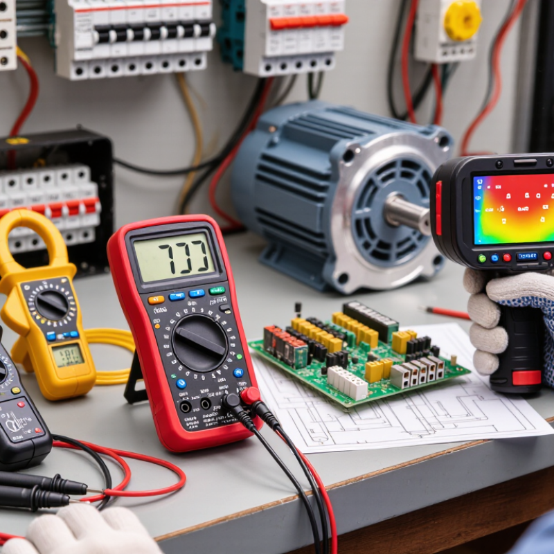
What Electrical Diagnostic Tools Measure and Analyze
Electrical diagnostic tools measure the values that reveal how a circuit is behaving. A digital multimeter checks voltage, current, resistance, and continuity at specific test points. Its continuity tone can help locate a broken wire, but it cannot confirm that the connection will carry a working load. Small clues matter.
A clamp meter measures current around an insulated conductor, while an oscilloscope displays voltage changes over time. These readings can expose brief voltage drops, noisy signals, or irregular pulses that a single meter reading may miss. Capacitance and frequency functions help assess components such as capacitors and motor circuits against their stated specifications. Thermal imaging can show uneven heat across a panel, though a hot spot alone does not identify its cause.
Measurements need context. A low voltage reading might indicate a weak supply, a poor connection, or simply the wrong test point. Technicians compare results with circuit diagrams, equipment ratings, and readings from related points. They also check meter settings and probe contact; small setup errors can produce convincing but misleading numbers. A reading is evidence, not a diagnosis.
