
What Is a Crawler Drive Motor and How Does It Work?
A Crawler Drive Motor is the component that turns hydraulic or electrical power into track movement. It helps a crawler machine push through mud, gravel, and uneven ground while maintaining controlled speed. The basic idea is straightforward. The engineering is not. Torque, gearing, seals, and heat all affect how reliably the machine moves.
Inside a hydraulic system, pressurized fluid enters the motor and drives its rotating group. The motor’s output passes through a reduction gearbox, which increases torque at the sprocket. The sprocket then pulls the track links forward. Picture a loaded excavator climbing a damp slope: steady track movement depends on more than motor power. The gearbox, hydraulic supply, and track condition matter too. Small leaks or overheating can become costly clues. They deserve attention.
This introduction will explain the motor’s main parts, operating cycle, and role in a crawler undercarriage. It will also cover performance factors, common symptoms, and practical maintenance checks. One limitation matters: no source article or verifiable expert quotation was provided, so I cannot responsibly attribute a direct quote to a named specialist. A useful engineering summary is: “A crawler drive motor converts available power into controlled track force, while its heat and response reveal how the system is performing.” It is concise, perhaps too neat. Real machines are messier, and diagnosis should consider the whole drive system.
What Is a Crawler Drive Motor and What Does It Do?
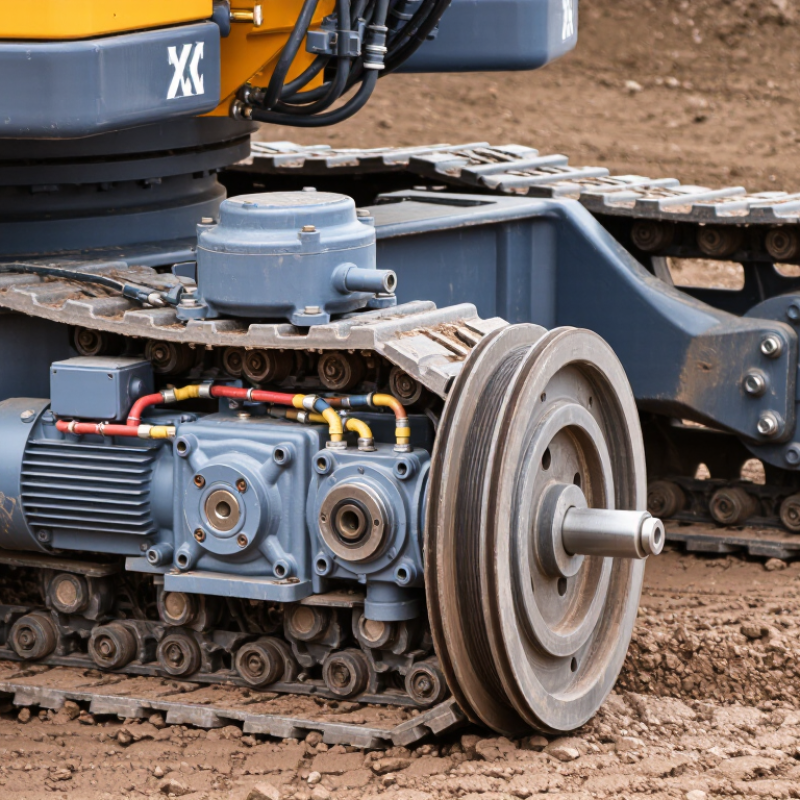
A crawler drive motor is the component that supplies motion to a tracked machine. It converts hydraulic pressure or electrical power into rotation. That rotation turns a reduction gearbox and drive sprocket, which pulls the track chain around its rollers. The track then pushes against the ground, moving the machine forward or backward. That is its job.
The motor also helps control travel speed and turning. On many machines, separate motors drive the left and right tracks. Slowing or reversing one side lets the machine pivot in a tight space. The gearbox reduces motor speed while increasing torque, which matters when a loaded machine climbs a slope or crosses soft soil. Some drive assemblies also include brakes to hold the machine when travel stops. Exact layouts vary, so the machine’s service information is the best guide.
Heat, leaks, unusual noise, or sluggish movement can point to trouble, but none proves the motor is faulty. A blocked filter or worn track may produce similar symptoms. A quick visual check can mislead. Measure pressure or electrical supply, inspect the track system, and compare results with the equipment specifications before replacing parts. That extra check is easy to skip. It can also prevent a costly mistake.
