
How to Choose the Right MPO Patch Cable
Choosing the right MPO Patch cable starts with the link, not the label. Count the fibers, identify the connector type, and confirm whether your equipment requires a pinned or unpinned connector. Check polarity, too. A cable can fit neatly and still route signals incorrectly. That small detail matters.
As an illustrative line—not a verified quotation—from fictional MPO specialist Elena Park: “Match the cable to the transceivers and polarity plan before you match it to the rack.” It is a useful reminder, though real installations may need more checks. Confirm single-mode or multimode fiber, connector gender, insertion-loss limits, and required length. A short run across a server rack has different handling needs from a longer backbone link. Look closely at the product specification sheet; “MPO-compatible” alone does not settle every detail.
This guide explains how to compare those choices without guessing. You will learn how fiber count, polarity method, and connector configuration affect compatibility. We will also cover inspection and cleaning, since a speck of dust on an end face can disrupt a clean-looking connection. Measure the route, allow gentle bends, and leave enough slack for service. Not too much. Cable choice is partly technical and partly practical, and that balance is easy to overlook. Verify the specifications against your transceivers and equipment documentation before ordering.
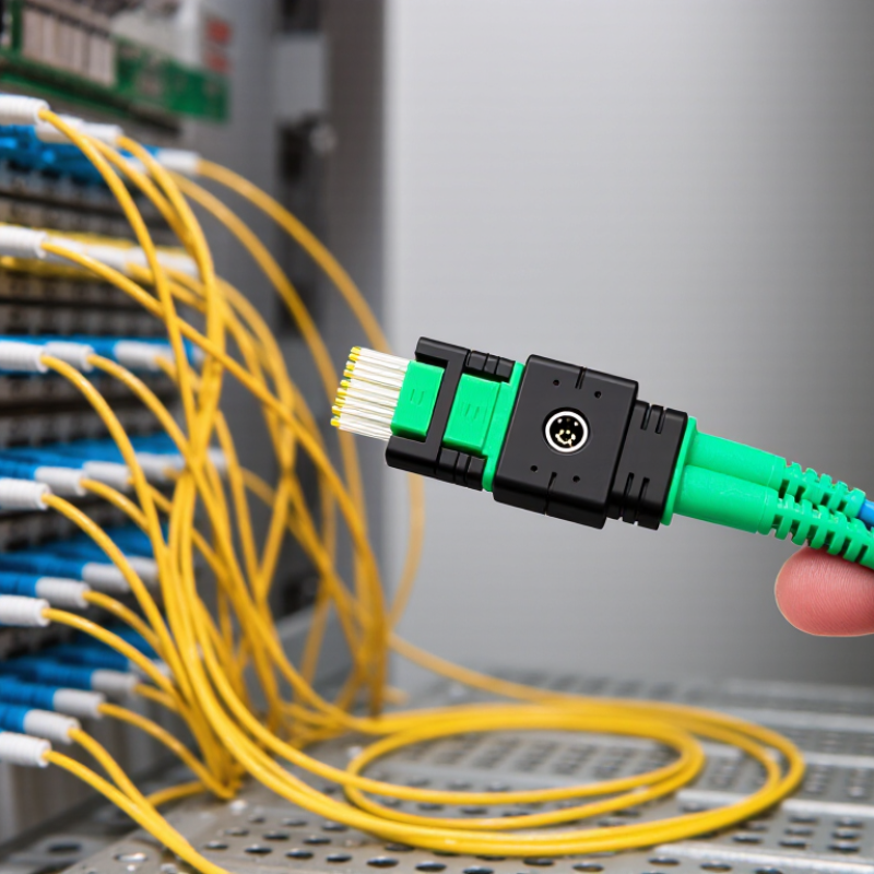
Identify the Application and Required Fiber Type
Before choosing an MPO patch cable, identify what the link connects, its speed, and its distance. A short switch-to-switch link may use multimode fiber, while longer building or campus runs often require single-mode OS2. Check the transceiver specifications too; the connector alone does not determine compatibility. Fiber type matters. Synergy Research Group’s 2024 data-center analysis projected global data-center capacity to more than double by 2030, reinforcing the need to plan cabling around actual growth and link requirements—not just today’s rack layout.
For multimode links, confirm the grade and supported reach. IEEE 802.3 specifications give 100GBASE-SR4 a maximum reach of 70 meters on OM3 and 100 meters on OM4. A few meters can change the right choice. For single-mode links, verify the optics’ wavelength and reach requirements before ordering OS2. Also check fiber count, polarity, and pin configuration against the equipment at both ends. These details are easy to overlook. A useful check is to compare the cable schedule with transceiver documentation and the labels on the installed equipment. It is tempting to assume matching MPO connectors mean matching fiber, but they do not. When documentation is incomplete, pause and verify rather than guessing.
