
How to Choose the Right 1.5HP Brushless Motor?
Choosing a 1.5hp Brushless Motor involves more than checking the power printed on its label. The right model must suit the load, operating speed, supply voltage, controller, and expected duty cycle. A motor driving a conveyor for hours faces different demands from one powering a small pump intermittently. Details matter.
Motor-drive researcher R. Krishnan, author of Electric Motor Drives: Modeling, Analysis, and Control, has written extensively about matching motors and drives. A practical takeaway from that work is to judge a motor by its operating requirements, not its headline rating alone. That distinction can prevent a costly mismatch. It is easy to overlook.
This guide explains how to compare rated and peak power, torque across the speed range, efficiency, cooling, mounting dimensions, and controller compatibility. It also highlights questions worth asking suppliers, such as whether the stated 1.5 horsepower is continuous or peak output. Check the datasheet against your real load, not an ideal one. A warm motor casing, a slow start, or a controller that trips can reveal problems calculations missed. I would not treat any single specification as decisive; product data can be incomplete, and actual performance depends on installation and use. The goal is a well-matched motor that delivers dependable output, not simply the most impressive number.
Identify the Application and Required Power Output
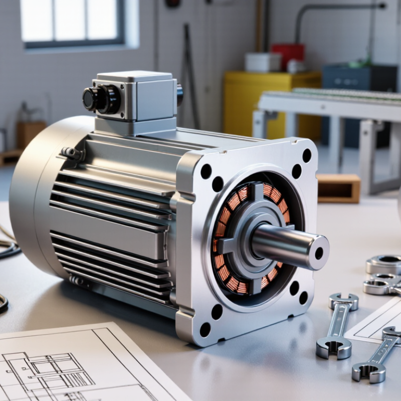
Choosing a 1.5 HP brushless motor starts with the job, not the catalog rating. A 1.5 HP output is about 1.12 kW, but that figure alone cannot tell you whether the motor suits a pump, conveyor, or ventilation fan. Estimate the load during normal operation, startup, and brief overloads. A pump pushing cold water may start differently from one moving a viscous fluid. Check required speed, shaft torque, operating hours, and available cooling space.
The International Energy Agency’s report Energy-Efficiency Policy Opportunities for Electric Motor-Driven Systems estimates that motor-driven systems use about 45% of global electricity. That scale makes correct application matching more than a sizing detail. For a fan running steadily, continuous power and efficiency matter; for a conveyor that starts under load, starting torque and controller limits may matter more. Allow for real operating conditions, but do not add a large safety margin without evidence. Oversizing can reduce efficiency at typical loads.
Check the motor’s rated output against the actual mechanical demand, then confirm voltage, speed range, duty rating, and thermal limits with its technical documentation. The U.S. Department of Energy’s motor-system guidance also emphasizes evaluating the complete drive system, not just the motor.
