
10 Best Component Terminal Blocks for Global Buyers
A Component Terminal Block may be small enough to sit between two fingers, yet it carries current, signals, and the consequences of a poor connection. For global buyers, choosing one means checking more than price: conductor range, rated voltage, vibration resistance, marking space, and installation method all matter. Small details matter.
The International Energy Agency’s Electricity 2024 report says global electricity demand grew by 2.2% in 2023 and forecasts faster growth through 2026. That expansion puts more pressure on dependable connections in control panels, buildings, and industrial equipment. Grand View Research’s terminal-block market analysis also tracks demand across application and product categories, a useful reminder that “best” depends on the installation, not just the catalogue ranking.
IEA Executive Director Fatih Birol described the shift with a concise phrase: “The Age of Electricity is upon us.” He is an energy-sector authority, not a terminal-block design specialist, so that quote signals the wider trend rather than product advice. For product decisions, buyers should verify current datasheets and applicable standards directly with manufacturers. A printed rating cannot reveal every field condition. This guide compares ten options by practical selection factors, including wiring convenience, mounting style, material, and support for international projects. One limitation remains: a shortlist cannot replace testing a sample in the actual panel, especially where heat, vibration, or frequent maintenance changes the demands.
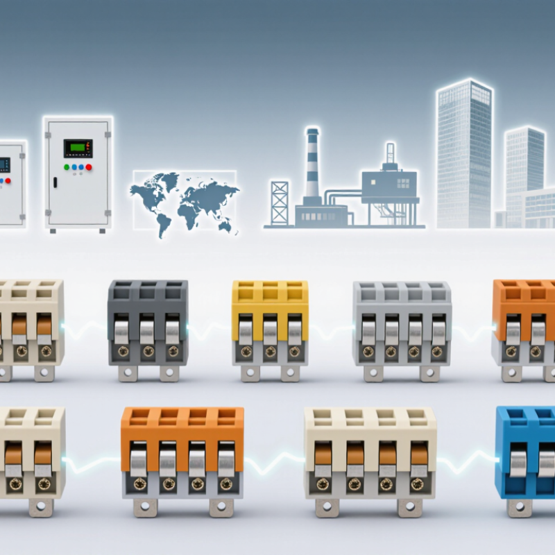
Understanding Component Terminal Blocks and Their Role
A component terminal block does more than join two wires. It provides a defined connection point and may include a function such as a fuse, indicator, diode, or disconnect. The exact function depends on its design, so check the product documentation rather than relying on appearance alone.
Small parts matter. A marker beside a fuse block can make fault checks quicker, while a loose screw clamp may cause heat or intermittent operation. Match the block’s wire range, rated current, voltage, and mounting method to the equipment. Also check conductor type and stripping length. These details are easy to miss on a crowded panel.
Fit the block to its working environment. Vibration, temperature, dust, and available space can affect performance and service access. Confirm that the terminal’s ratings cover the intended conditions, and leave room for safe wiring and inspection. There is no universally best component terminal block. A compact option may save space but make maintenance awkward. Selection is not always neat; sometimes the best choice becomes clear only after checking the wiring layout and the task technicians will perform.
| Terminal Block Type | Typical Connection and Mounting | Common Conductor Range | Typical Use | Key Selection Consideration |
|---|---|---|---|---|
| Screw-clamp feed-through | Screw connection; commonly mounted on a DIN rail | About 0.2–35 mm², depending on the terminal size | General wiring distribution in control cabinets and machinery | Check conductor size, tightening torque, rated current, and whether the design accepts ferrules. |
| Spring-clamp feed-through | Spring pressure connection; commonly DIN-rail mounted | About 0.2–16 mm² in common product ranges | Control panels subject to vibration or frequent wiring work | Confirm the permitted conductor types and whether a tool is needed for insertion or release. |
| Push-in feed-through | Tool-free insertion for compatible conductors; commonly DIN-rail mounted | Often about 0.14–10 mm², varying by design | High-density control wiring and installations where fast termination is useful | Verify compatibility with solid, stranded, or ferruled conductors as specified by the manufacturer. |
| Double-level terminal block | Two stacked connection levels in one block; commonly DIN-rail mounted | Often about 0.2–6 mm² per connection point | Compact panel wiring where multiple circuits must fit in limited rail space | Check circuit separation, marking space, jumper options, and access to each level. |
| Protective-earth (PE) terminal block | Conductive connection to a DIN rail or designated grounding system | Commonly selected to match the installation’s protective conductor size | Protective bonding and grounding in electrical enclosures | Confirm the required fault-current performance, rail compatibility, and applicable safety approvals. |
| Fuse terminal block | Fuse holder integrated into a terminal block; often DIN-rail mounted | Typically designed for control-circuit conductor sizes | Overcurrent protection for control, signal, or auxiliary circuits | Match the fuse type and rating to the circuit; check indication features and safe fuse replacement access. |
| Disconnect or test terminal block | Includes a disconnect point or test access; commonly DIN-rail mounted | Varies by terminal size and connection technology | Measurement, troubleshooting, and circuit isolation in control systems | Check the switching method, test-probe compatibility, and whether the terminal is rated for the intended circuit. |
| PCB screw terminal block | Soldered directly to a printed circuit board; wire secured by screw | Often about 0.2–6 mm², depending on pitch and design | Field wiring connections on power supplies, controllers, and electronic equipment | Confirm pin pitch, PCB footprint, wire-entry direction, and board-level current and voltage limits. |
| Pluggable PCB terminal block | Board-mounted header mates with a removable wire connector | Commonly intended for small-to-medium control conductors | Equipment that benefits from removable wiring during servicing or assembly | Verify mating compatibility, pole count, pitch, locking method, and the electrical rating of the complete connector pair. |
| Barrier terminal block | Screw terminals separated by insulating barriers; panel or chassis mounted | Available in a wide range, from small control wiring to larger conductors | Power distribution and equipment connections where visible separation is useful | Review spacing, mounting method, conductor range, cover requirements, and applicable regional standards. |
| Buyer note: These are common terminal-block types, not a universal product ranking. Conductor ranges and electrical ratings vary by model, material, ambient conditions, wiring method, and approval standard. Confirm the manufacturer’s datasheet and the requirements applicable in the destination market before selection. | ||||
